

All switches will be running RSTP in this demonstration, and I will look at the Proposal / Agreement process both from a Root and non-Root Bridges perspective!
RSTP Synchronization Process via Proposals and Agreements
When an RSTP enabled switch first comes online, it sets all ports into a Designated / Blocking “Discarding” state, while it sends Proposal frames out all non-Edge interfaces.
The Local switch will send out “Proposals” to all RSTP neighbor switches telling them it is the Root Bridge, and if it is correct, they will send back an Agreement and “Synchronize” their RSTP interfaces accordingly.
If the receiving switch does not Agree with the remote switches Proposal, it will send back a Superior BPDU to the remote switch, and the remote switch will adjust its interfaces dynamically given the Superior BPDUs received.
It is not so much aimed at finding or electing a Root Bridge, though this happens during the process, however it is more of a Root Path detection through the network (and a way for ports to be selected for Forward or Blocking states).
My personal way of understanding and remembering RSTP Synchronization
To understand and remember this process, I think of it as a bunch of rough necks walking into a room, looking to fight the toughest guy in the place.
Each person looks at their neighbor and throws a punch (Proposal) to see who’s tougher, at which point the neighbor either takes the punch and admits defeat (Agreement) or throws a stronger punch back (Superior BPDU) to the original tough guy forcing them to adjust their attitude (Root Path)!
This series of people punching each other continues until the toughest person in the room is determined (Root Bridge), everyone determines which neighbors they are tougher than (Root Path), until everyone stops punching each other and now knows their place in the pecking order of getting punched.
Its kind of an odd way to look at a CCNP SWITCH topic, but it works to keep make an otherwise drab process stick in my head, so hopefully it will work for you too 🙂
This process I’ve found is easier to understand through debugs / illustration
For this I will demonstrate on SW1, as it is the Root Bridge, and easier to illustrate via debugging output.
Interface Range Fa1/0/1 – 5 were shut down, and upon coming back up, the debugging output came back as follows from SW1:
SW1(config-if-range)#
SW1(config-if-range)#do debug span events
Spanning Tree event debugging is on
SW1(config-if-range)#
SW1(config-if-range)#no shut
SW1(config-if-range)#
*Mar 1 01:30:54.214: %LINK-3-UPDOWN: Interface FastEthernet1/0/1, changed state to down
*Mar 1 01:30:54.222: %LINK-3-UPDOWN: Interface FastEthernet1/0/2, changed state to down
*Mar 1 01:30:54.230: %LINK-3-UPDOWN: Interface FastEthernet1/0/3, changed state to down
*Mar 1 01:30:54.239: %LINK-3-UPDOWN: Interface FastEthernet1/0/4, changed state to down
*Mar 1 01:30:54.255: %LINK-3-UPDOWN: Interface FastEthernet1/0/5, changed state to up
SW1(config-if-range)#
*Mar 1 01:30:55.010: setting bridge id (which=3) prio 24577 prio cfg 24576 sysid 1 (on) id 6001.1ce6.c7c1.c800
*Mar 1 01:30:55.010: RSTP(1): initializing port Fa1/0/3
*Mar 1 01:30:55.010: RSTP(1): Fa1/0/3 is now designated
*Mar 1 01:30:55.019: RSTP(1): transmitting a proposal on Fa1/0/3
SW1(config-if-range)#
*Mar 1 01:30:57.007: %LINK-3-UPDOWN: Interface FastEthernet1/0/3, changed state to up
*Mar 1 01:30:57.108: setting bridge id (which=3) prio 24577 prio cfg 24576 sysid 1 (on) id 6001.1ce6.c7c1.c800
*Mar 1 01:30:57.108: RSTP(1): initializing port Fa1/0/5
*Mar 1 01:30:57.108: RSTP(1): Fa1/0/5 is now designated
*Mar 1 01:30:57.116: RSTP(1): transmitting a proposal on Fa1/0/5
SW1(config-if-range)#
*Mar 1 01:30:57.250: %LINK-3-UPDOWN: Interface FastEthernet1/0/1, changed state to up
*Mar 1 01:30:58.047: RSTP(1): initializing port Fa1/0/3
*Mar 1 01:30:58.047: RSTP(1): Fa1/0/3 is now designated
*Mar 1 01:30:58.056: RSTP(1): transmitting a proposal on Fa1/0/3
*Mar 1 01:30:58.081: RSTP(1): received an agreement on Fa1/0/3
*Mar 1 01:30:58.081: STP[1]: Generating TC trap for port FastEthernet1/0/3
*Mar 1 01:30:58.089: RSTP(1): transmitting a proposal on Fa1/0/5
*Mar 1 01:30:58.097: RSTP(1): received an agreement on Fa1/0/5
SW1(config-if-range)#
*Mar 1 01:30:58.097: STP[1]: Generating TC trap for port FastEthernet1/0/5
*Mar 1 01:30:58.106: %LINEPROTO-5-UPDOWN: Line protocol on Interface FastEthernet1/0/5, changed state to up
*Mar 1 01:30:58.290: RSTP(1): initializing port Fa1/0/1
*Mar 1 01:30:58.290: RSTP(1): Fa1/0/1 is now designated
*Mar 1 01:30:58.299: RSTP(1): transmitting a proposal on Fa1/0/1
*Mar 1 01:30:59.045: %LINEPROTO-5-UPDOWN: Line protocol on Interface FastEthernet1/0/3, changed state to up
SW1(config-if-range)#
*Mar 1 01:30:59.289: %LINEPROTO-5-UPDOWN: Line protocol on Interface FastEthernet1/0/1, changed state to up
*Mar 1 01:30:59.331: RSTP(1): transmitting a proposal on Fa1/0/1
*Mar 1 01:30:59.339: RSTP(1): received an agreement on Fa1/0/1
*Mar 1 01:30:59.339: STP[1]: Generating TC trap for port FastEthernet1/0/1
SW1(config-if-range)#
Highlighted in pink is the interface initializing / moving into Designated (Discarding), immediately followed by starting to send Proposals out the interface highlighted in red, then highlighted in blue is the “Agreement” received on each interface as this IS the Root Bridge!
Note that Proposals are being sent once every 1 second until an Agreement is received, and once an Agreement is received for the interface the Line Protocol is then brought up on that interface.
To illustrate the above debug process is a couple of simple and quick MS Paint diagrams:

Proposals sent out all non-Edge Ports as the became initialized in RSTP

Received Agreements on ALL interfaces because SW1 has the Superior STP BID / BPDU.
A different scenario focusing on SW3, and removing the link from SW4 to SW1!
To give a different perspective on this, I’ve removed the cable between SW1 and SW4:

Now for the output shown from doing a “shut” on interface range fa1/0/2 – 4
SW3(config-if-range)#no shut
SW3(config-if-range)#
*Mar 1 02:05:15.118: %LINK-3-UPDOWN: Interface FastEthernet1/0/2, changed state to up
*Mar 1 02:05:15.127: %LINK-3-UPDOWN: Interface FastEthernet1/0/3, changed state to up
*Mar 1 02:05:15.135: %LINK-3-UPDOWN: Interface FastEthernet1/0/4, changed state to up
SW3(config-if-range)#
*Mar 1 02:05:17.887: RSTP(1): initializing port Fa1/0/2
*Mar 1 02:05:17.887: RSTP(1): Fa1/0/2 is now designated
*Mar 1 02:05:17.895: RSTP(1): initializing port Fa1/0/3
*Mar 1 02:05:17.895: RSTP(1): Fa1/0/3 is now designated
*Mar 1 02:05:17.895: RSTP(1): updt roles, received superior bpdu on Fa1/0/3
*Mar 1 02:05:17.895: RSTP(1): Fa1/0/3 is now root port
*Mar 1 02:05:17.895: RSTP(1): syncing port Fa1/0/2
*Mar 1 02:05:17.895: RSTP(1): synced Fa1/0/3
*Mar 1 02:05:17.895: RSTP(1): transmitting a proposal on Fa1/0/2
SW3(config-if-range)#
*Mar 1 02:05:17.903: STP[1]: Generating TC trap for port FastEthernet1/0/3
*Mar 1 02:05:17.903: RSTP(1): transmitting an agreement on Fa1/0/3 as a response to a proposal
*Mar 1 02:05:17.928: RSTP(1): transmitting a proposal on Fa1/0/2
*Mar 1 02:05:17.928: RSTP(1): initializing port Fa1/0/4
*Mar 1 02:05:17.928: RSTP(1): Fa1/0/4 is now designated
*Mar 1 02:05:17.937: RSTP(1): transmitting a proposal on Fa1/0/4
*Mar 1 02:05:17.945: RSTP(1): received an agreement on Fa1/0/4
SW3(config-if-range)#
*Mar 1 02:05:17.945: STP[1]: Generating TC trap for port FastEthernet1/0/4
*Mar 1 02:05:17.954: RSTP(1): transmitting a proposal on Fa1/0/2
*Mar 1 02:05:18.558: RSTP(1): transmitting a proposal on Fa1/0/2
*Mar 1 02:05:18.868: %LINEPROTO-5-UPDOWN: Line protocol on Interface FastEthernet1/0/2, changed state to up
*Mar 1 02:05:18.885: %LINEPROTO-5-UPDOWN: Line protocol on Interface FastEthernet1/0/3, changed state to up
*Mar 1 02:05:18.885: RSTP(1): updt roles, received superior bpdu on Fa1/0/2
SW3(config-if-range)#
*Mar 1 02:05:18.885: RSTP(1): Fa1/0/2 is now alternate
*Mar 1 02:05:18.927: %LINEPROTO-5-UPDOWN: Line protocol on Interface FastEthernet1/0/4, changed state to up
SW3(config-if-range)#
So instead of all Proposals and Agreements, we now have Superior BPDU’s in the mix of the Synchronization process with a new color highlighted in green.
Note that SW1 (Fa1/0/3) did not even have a Proposal sent out the interface, it just received a Superior BPDU, then sent an Agreement back as though it was sent a Proposal.
Also on Fa1/0/2 it DID send out Proposals, but because SW2 does not see SW3 as the Root Bridge or the Root Path, it sends back a Superior BPDU so that SW3 puts its end of the link in Alternate / Blocking state.
Here is a rough illustration of the exchange:
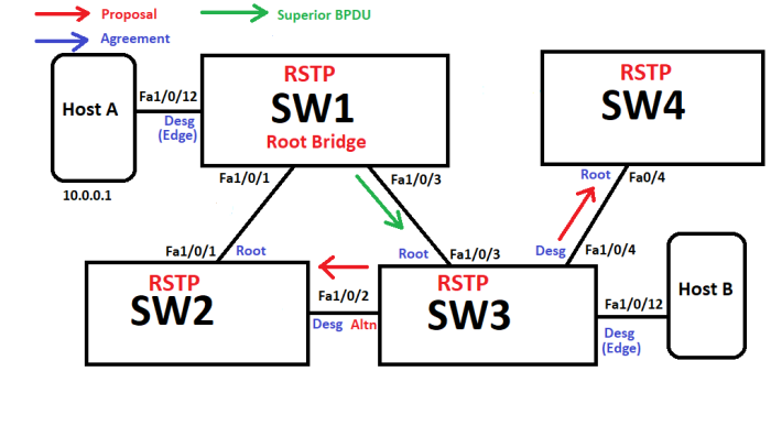
SW initially and periodically sends Proposals out int Fa1/0/2 and Fa1/0/4, however it immediately received a Superior BPDU from the Root Bridge.

So the following occurs in response to the first phase of Superior BPDUs and Proposals:
- SW3 sends its own Agreement to a Proposal from SW1 that it is the Root Path
- SW4 sends an Agreement to SW3’s Proposal, as it is the only Root Path possible
- SW2 responds to the Proposal from SW3 with a Superior BPDU, indicating it has a better Root Path, and SW3 adjusts the interface accordingly
So if a Switch receiving a Proposal Agrees the sender is the Root Path, it will send an Agreement back, otherwise it will send a Superior BPDU back for the switch to use in setting its interface STP states.
This will continue through the entire switched network, the Root Path being negotiated through Proposals / Agreements / Superior BPDUs until the network is Synchronized.
One larger scale Topology theory to end the Synchronization discussion
With the smaller example above, I wanted to visually demonstrate that Superior BPDU curve ball in the Proposal / Agreement process, however going from the Root Bridge out it would look like this:
First Proposal / Agreement starting at Root Bridge

Root Bridge synchronized to both connected switches

The non-Root Bridges then send / receive Proposals / Agreements to connected switches

The non-Root Bridges are now fully synchronized

Etc
Every switch in this process is “Synchronized” once it finishes its Proposal / Agreement process, so by looking at this Topology the Root Bridge and the two switches below it are Synchronized, while the rest of the Etc network portion needs to keep running this convergence process until the network achieves Full Synchronization!
One last note on this topic, Root Bridge and Port State election is the same with RSTP vs STP, the only difference is timers (or lack thereof in RSTP) – So keep in mind the same Criteria for Root Bridge election and Port State selection is the same for both flavors of STP!
