

The above Topology is configured waaaay toward the bottom of the post, there is a lot of ground to cover in terms of the evolution of STP, and clarifying some differences in flavors.
I have spent days researching Cisco documentation / Blogs / Discussions / Training material to cross reference MST information, as this is a very complex topic with quite a bit of conflicting information even from Cisco.
I assume this is enough knowledge to get by the CCNP SWITCH exam, but this is far from an exhaustive review on all topics relating to Multiple Spanning-Tree, so I definitely encourage using multiple sources for in depth study of MST!
Common Spanning-Tree (CST) – The beginning of STP!
To review MST you must start at the beginning of STP’s existence, which is an industry standard across all switch vendors called “Common Spanning-Tree”, which uses IEEE 802.1q Trunks to run a single STP instance for all VLANs over Trunk ports.
With “Common” Spanning-Tree or CST the name is really the recipe, as one “Common” Spanning-Tree instance exists for all VLANs on the switch, which looking at different STP names they also come more full circle
- CST = One “common” instance for all VLANs (802.1q)
- PVST = One instance “Per VLAN” (802.1d)
- RSTP / RPVST = “Rapid PVST” (802.1w)
- MST = “Multiple” Spanning-Tree instances (802.1s)
So that really illustrates the evolution of STP in those four bullet points
- CST = Created to give any sort of Layer 2 Loop Detection / Prevention
- PVST = Created to give full control Per VLAN for Layer 2 traffic flow
- RSTP = Created to allow faster PVST convergence
- MST = Created to address hardware resource utilization of PVST
CST in essence can be summed up with this simple Topology:
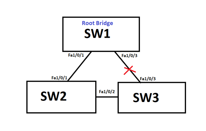
Every trunk link treats all VLANs in one certain way, load-balancing is not possible with CST, what you see above is the extent of what it does!
One thing I must point out on the CLI:
SW1(config)#span mode ?
mst Multiple spanning tree mode
pvst Per-Vlan spanning tree mode
rapid-pvst Per-Vlan rapid spanning tree mode
This confused the daylights out of me, if it was not configurable than WHERE IS IT?
CST is not a configurable STP mode in general, however its common STP instance concept is used with MST – More on this in the MST segment.
A quick word on the oddity of the IEEE definition of CST
Per Cisco’s official documentation, CST was introduced and defined by IEEE 802.1Q (Dot1q Trunking), so this is the standard I would tend to go with if asked on exam day, however if you research this on forums many highly respected members of the community call CST “Legacy STP” and advise it is defined under IEEE 802.1d STP.
This seems amazingly not agreed upon by the Cisco community, but for exam day, I would personally go with Cisco’s documentation that it is defined in IEEE 802.1Q.
One final note on Cisco’s cover up of the acronym MST – Mono Spanning-Tree:
Cisco acknowledges MST both as Mono-Spanning Tree noted here:
“Non-Cisco 802.1Q switches maintain only a single instance of spanning tree (the Mono Spanning Tree, or MST) that defines the spanning tree topology for all VLANs. When you connect a Cisco switch to a non-Cisco switch through an 802.1Q trunk, the MST of the non-Cisco switch and the native VLAN spanning tree of the Cisco switch combine to form a single spanning tree topology known as the Common Spanning Tree (CST).”
Source- Cisco configuration pdf doc – I advise using ctrl + f and searching for mono.
On the other hand, Cisco notes MST as meaning Multiple Spanning-Tree not only in IOS Help but also in their Acronym library found here:
They reference different switch platforms, and I am not sure if that will come into play on exam day, but it is worth noting that MST may refer to a “Mono Spanning-Tree” instance rather than Multiple Spanning-Tree.
PVST vs PVST+ – The evolution continues!
Per VLAN Spanning-Tree is the evolution of CST, breaking one common instance of STP into all separate running instances, which gives the network administrator total control of configuring specific traffic flows for VLANs throughout the switched network.
This topic really confused me, and many other people, because on the CLI:
SW1(config)#span mode ?
mst Multiple spanning tree mode
pvst Per-Vlan spanning tree mode
rapid-pvst Per-Vlan rapid spanning tree mode
Much alike CST, PVST+ is nowhere to be seen, and that is because this ALSO is not a configurable STP mode – It is PVST running over either ISL or 802.1Q Trunks.
“PVST” is Cisco Proprietary and only operates on ISL Trunks, whereas “PVST+” can operate on either ISL or 802.1q Trunks, and that is really the difference on whether it is PVST or PVST+ being run.
Remember that ISL has major overhead by encapsulating the ENTIRE FRAME with a header and trailer, sometimes referred to as “double-tagging” the frame, and ISL Trunks do not recognize the “Native VLAN” (All untagged traffic goes to Native VLAN) concept.
Most trunks are dot1q so its generally just called PVST without the + at the end, but for the purposes of a Cisco exam, the difference of PVST and PVST+ is the trunk type.
— An example of this info being handy on exam day —
“Refer to the exhibit. What type of trunk mode can the following two interfaces be in? Select all answers that apply”
SW1#sh int trunk
Port Mode Encapsulation Status Native vlan
Fa1/0/1 on 802.1q trunking 1
Fa1/0/3 auto n-802.1q trunking 1
- RSTP – Correct
- MSTP – Correct
- PVST – FALSE!
- PVST+ – Correct
This is a question I just created myself to demonstrate what you may see on exam day, so it is important to fully understand this concept for exam day!
To illustrate what I’ve posted before in depth here about load balancing but also drew up a simple illustration of the traffic manipulation more for comparison to MST:

With the above configuration, PVST+ is running across 802.1q trunks, and as seen I’ve made SW3 the Root Bridge for VLANs 50 and 60 with the following commands:
SW3(config)#span vlan 50 root primary
SW3(config)#span vlan 60 root primary
This is what PVST was made for, as only SW3 has Uplinks from VLANs 50 and 60, so if traffic destined for it hits SW2 it doesn’t need to go up to SW1 being the “default” Root Bridge and back down to SW3 – In this way PVST allows for Layer 2 traffic manipulation!
RSTP works the same of course with the differences covered here as PVST, so I will not re-hash that entire post here, as it operates the same a PVST, to the point that it is actually called RPVST or Rapid-PVST in IOS help:
SW1(config)#span mode ?
mst Multiple spanning tree mode
pvst Per-Vlan spanning tree mode
rapid-pvst Per-Vlan rapid spanning tree mode
I know its a CCNA level note, but a good refresher that come exam day STP versions will probably be shown as RPVST+ and not simply RSTP as I would call it, something to mentally prepare on for exam day if you’re not fresh out of CCNA training.
Multiple Spanning-Tree Protocol – MST or MSTP depending on who you ask!
MST is defined by IEEE 802.1s Multiple Spanning-Tree Protocol, which allows the mapping of multiple VLANs to single instances of STP, which allows for the middle ground of CST and PVST in terms of STP Instances.
MST is an Enterprise level solution for a network with hundreds or thousands of VLANs, where running one instance of STP Per VLAN isn’t feasible, so that one Physical Topology of connected switches can be broken up logically into what is called “Regions” to handle certain STP Instances and the VLANs mapped to them.
MST switches behave exactly like RSTP in terms of Root Bridge election by using the same Proposal / Agreement system, originating their own BPDUs or Hellos every 2 seconds, and electing a Root Bridge per Region by lowest Bridge ID + MAC (BID).
What is an MST Region?
MST Regions are Physical switch Topologies, which are broken up into Logical switch Topologies, by configuring MST instances on each switch.
For switches to be considered in the same Region, the following values must match:
- MST Config Name – Configured in MST configuration mode
- MST Config Revision # – Manually configured in MST configuration mode
- MST Instance / VLAN Mapping Table – This is actually a digest that is derived from the contents of the Mapping-Table, the entire Mapping-Table itself IS NOT SENT VIA MST BPDU!
These 3 values in the MST BPDUs must match among neighboring switches, if a switch receives mismatched information, it is considered in another Region.
To take that a step further if a switch receives mismatching information or detects a different Version number in the BPDU, the port that BPDU was received on is designated as a Boundary Port, and the switch containing the Boundary Port is referred to as a Boundary Switch for that IST / Region.
In terms of Version #’s that have been reviewed in STP posts:
- STP = Version # 0
- RSTP = Version # 2
- MSTP = Version # 3
Speaking of IST’s and Regions, I’ll discuss that as briefly as possible for a moment.
What is an IST?
The Region contains an IST (Internal Spanning-Tree) instance by default, which is Instance 0 / MSTI 0 (Multiple Spanning-Tree Instance), and initially has all VLANs are mapped to the IST.
It is referred to as “The IST” because it is a specialized / designated instance in a Region for communicating STP related information, and is responsible for keeping optimal loop-free paths within the Region, but also the important function of creating MSTI BPDUs that generate the Hash of the VLAN Mapping Table that switches must agree on to become part of that Region.
So the IST not only keeps optimal loop-free paths, but also communicates information between all the Instances within a Region.
What is an MSTI?
MSTI’s are any MST Instance configured in addition to IST 0, all MSTI’s are mapped to the CIST (Common Internal Spanning-Tree) instance at the Boundary Ports, though MSTI Trees are constructed independently of each other.
What is a CIST and where does CST fit into all this?
CIST is on the Regions Boundary switch / Boundary ports (all non-Boundary IST ports are just called Internal ports), which receives the MSTI Mappings from the ISTs of the Region, to allow for communication among the entire Bridged Topology and allowing for multiple Regions to communicate with each other.
CST allows for the IST or MST Region to be seen by the STP / RSTP network segments as a single Logical Bridge, and allows for communication between the MST Region and the non-MST switched network.
To illustrate how this all falls into place, I’ve created the following diagram:

The MSTIs are mapped to the Boundary Ports / CISTs, as they may either connect to an upstream CST Boundary switch that talks to the STP / RSTP segment of the network, or they may connect directly to different Regions.
Essentially the above Topology can be broken down into this Topology:

This type of Topology represents a single Region connecting to a CST enabled Bridge, allowing for this Region to communicate with STP / RSTP instances.
For Region to Region communication, it is important to note that all Ports in the following Topology are considered Boundary Ports:

Yes I put little purple BP’s on every link to drive that point home, and I also added some links move into Blocking state, as there is a Regional / CIST Root Bridge Election that is far more detailed beyond the scope of CCNP (I hope) and will not be reviewed here.
Some final notes on MST and its backwards compatibility with PVST / PVST+ / RSTP:
- MST is NOT backwards compatible with PVST because it requires dot1q Trunks
- MST is backwards compatible with PVST+, but will slow down convergence due to changing its behavior to adhere to Forward Delay timers with its PVST+ neighbor
- MST is backwards compatible with RSTP
With that a look at the CLI commands to configure MST, and verification!
I will be configuring (or attempting to configure) the following Topology on my lab:
This represents one Physical Topology shown by the black lines representing the dot1q Trunks, along with color coded instances that will be mapped along the way!
To begin, we put SW1 into Spanning-Tree MST Mode:
SW1(config)#span mode ?
mst Multiple spanning tree mode
pvst Per-Vlan spanning tree mode
rapid-pvst Per-Vlan rapid spanning tree mode
SW1(config)#span mode mst ?
<cr>
SW1(config)#span mode mst
So this bounced some links as no other switches are configured at all yet for MST, the next step is moving into MST Configuration Mode:
SW1(config)#span ?
backbonefast Enable BackboneFast Feature
etherchannel Spanning tree etherchannel specific configuration
extend Spanning Tree 802.1t extensions
logging Enable Spanning tree logging
loopguard Spanning tree loopguard options
mode Spanning tree operating mode
mst Multiple spanning tree configuration
pathcost Spanning tree pathcost options
portfast Spanning tree portfast options
transmit STP transmit parameters
uplinkfast Enable UplinkFast Feature
vlan VLAN Switch Spanning Tree
SW1(config)#span mst ?
WORD MST instance range, example: 0-3,5,7-9
configuration Enter MST configuration submode
forward-time Set the forward delay for the spanning tree
hello-time Set the hello interval for the spanning tree
max-age Set the max age interval for the spanning tree
max-hops Set the max hops value for the spanning tree
SW1(config)#span mst config
SW1(config-mst)#
So “span mst config” gets to the config-mst prompt to configure the MST Region, but I also highlighted in blue the “WORD / MST Instance #” portion, as it seems like a good thing to know as well:
SW1(config)#span mst 1 ?
priority Set the bridge priority for the spanning tree
root Configure switch as root
This is basically “Rigging the Election” when it comes to making this switch the Root Bridge for this MST Region.
There are other values that can be changed for the local switch such as Hello / Forward Delay / Max-Age just like any STP Bridge, however there is a Max Hops value that is contained within the MST BPDUs that configuration is beyond the scope of CCNP but is good to know where it is and that it exists.
Back to configuration, lets look at our options:
SW1(config-mst)#?
abort Exit region configuration mode, aborting changes
exit Exit region configuration mode, applying changes
instance Map vlans to an MST instance
name Set configuration name
no Negate a command or set its defaults
private-vlan Set private-vlan synchronization
revision Set configuration revision number
show Display region configurations
SW1(config-mst)#
Highlighted in red are the 3 values that must match for two switches to be in the same Region, highlighted in blue are the two ways of exiting MST configuration mode, and highlighted in green demonstrates that there is a sub-set of “show” commands within this configuration prompt:
SW1(config-mst)#show ?
current Display mst configuration currently used
pending Display the new mst configuration to be applied
<cr>
ONE VERY IMPORTANT NOTE WITH THE SHOW COMMAND FOR EXAM DAY!
“show” and “show pending” will produce the same output, this is the “pending” configuration that is currently being entered, which is erased if you use the “abort” option in this mode.
You MUST be in config-mst mode to see a “Pending” MST configuration, it is NOT viewable from the User Exec prompt!
That is a huge Cisco Gotcha for exam day, so really commit that to memory for exam day!
To illustrate the “show” command:
SW1(config-mst)#show
Pending MST configuration
Name []
Revision 0 Instances configured 1
Instance Vlans mapped
——– ———————————————————————
0 1-4094
——————————————————————————-
SW1(config-mst)#
It is completely blank except for IST instance 0 running with all VLANs mapped to it as per the default.
So lets make some MSTIs on SW1 per the above Topology:
Configuring the 3 MSTIs
SW1(config-mst)#instance ?
<0-4094> MST instance id
SW1(config-mst)#instance 1 ?
vlan Range of vlans to add to the instance mapping
SW1(config-mst)#instance 1 vlan ?
LINE vlan range ex: 1-65, 72, 300 -200
SW1(config-mst)#instance 1 vlan 10-20 ?
LINE <cr>
SW1(config-mst)#instance 1 vlan 10-20
SW1(config-mst)#instance 2 vlan 30-40
SW1(config-mst)#instance 3 vlan 50-60
SW1(config-mst)#
Configuring the Revision #
SW1(config-mst)#revision ?
<0-65535> Configuration revision number
SW1(config-mst)#revision 1 ?
<cr>
SW1(config-mst)#revision 1
^The Revision # has to be manually configured, does NOT dynamically update like VTP!
Configuring the Name
SW1(config-mst)#name ?
WORD Configuration name
SW1(config-mst)#name CCNP ?
<cr>
SW1(config-mst)#name CCNP
Verification – “show pending”
SW1(config-mst)#show pending
Pending MST configuration
Name [CCNP]
Revision 1 Instances configured 4
Instance Vlans mapped
——– ———————————————————————
0 1-9,21-29,41-49,61-4094
1 10-20
2 30-40
3 50-60
——————————————————————————-
SW1(config-mst)#
Verification – “show current”
SW1(config-mst)#show current
Current MST configuration
Name []
Revision 0 Instances configured 1
Instance Vlans mapped
——– ———————————————————————
0 1-4094
——————————————————————————-
SW1(config-mst)#
So this tells us that we have some great configurations that are pending, but have not yet been processed, and this is because of those top two lines in IOS help from MST Config:
SW1(config-mst)#?
abort Exit region configuration mode, aborting changes
exit Exit region configuration mode, applying changes
So if you do not want to change anything, you type abort, otherwise you can either use exit or my favorite keyboard shortcut “ctrl + z” and it will apply your changes, which will then show up now under “show current”:
SW1(config-mst)#show current
Current MST configuration
Name [CCNP]
Revision 1 Instances configured 4
Instance Vlans mapped
——– ———————————————————————
0 1-9,21-29,41-49,61-4094
1 10-20
2 30-40
3 50-60
——————————————————————————-
SW1(config-mst)#
As mentioned above a “Current” configuration can be seen from User exec level here:
SW1#sh span mst config
Name [CCNP]
Revision 1 Instances configured 4
Instance Vlans mapped
——– ———————————————————————
0 1-9,21-29,41-49,61-4094
1 10-20
2 30-40
3 50-60
——————————————————————————-
SW1#
It does have a lot of other useful and more detailed verification commands in there, however I wanted to focus on showing this as
There is always “show span” as well to review some details, however the values contained here are quite different from normal STP / RSTP:
SW1#sh span
MST0
Spanning tree enabled protocol mstp
Root ID Priority 32768
Address 1ce6.c7c1.c800
This bridge is the root
Hello Time 2 sec Max Age 20 sec Forward Delay 15 sec
Bridge ID Priority 32768 (priority 32768 sys-id-ext 0)
Address 1ce6.c7c1.c800
Hello Time 2 sec Max Age 20 sec Forward Delay 15 sec
Interface Role Sts Cost Prio.Nbr Type
——————- —- — ——— ——– ——————————–
Fa1/0/1 Desg FWD 200000 128.3 P2p Bound(PVST) *PVST_Inc
Fa1/0/3 Desg FWD 200000 128.5 P2p Bound(PVST) *PVST_Inc
After configuring MST it shows the interface Types as “Bound(PVST)” and moved them into a PVST_Inc state which can be verified via “show span inconsistent” command, though I will spare the output as it shows two entries (for each interface) for every MSTI.
At the top of the output it clearly shows that MSTP is running, and what I get from “sh span” instead of 7 different instances for VLAN 1,10,20,30,40,50,60 I get 4 STP Instances marked (at the very top of the output) in the format of MST0 / MST1 / Etc rather than VLAN0001, VLAN0002, etc.
Now to configure the rest of the network!
SW2 MST Config
SW2>en
SW2#conf t
Enter configuration commands, one per line. End with CNTL/Z.
SW2(config)#span mode mst
SW2(config)#span mst config
SW2(config-mst)#name CCNP
SW2(config-mst)#revision 1
SW2(config-mst)#instance 1 vlan 10-20
SW2(config-mst)#instance 2 vlan 30-40
SW2(config-mst)#instance 3 vlan 50-60
SW2(config-mst)#^Z
SW2#
SW3 MST Config
SW3>en
SW3#conf t
Enter configuration commands, one per line. End with CNTL/Z.
SW3(config)#span mode mst
SW3(config)#span mst config
SW3(config-mst)#name CCNP
SW3(config-mst)#revision 1
SW3(config-mst)#instance 1 vlan 10-20
SW3(config-mst)#instance 2 vlan 30-40
SW3(config-mst)#instance 3 vlan 50-60
SW3(config-mst)#^Z
SW3#
*Mar 1 03:21:18.127: %SYS-5-CONFIG_I: Configured from console by console
SW3#
When returning to SW1 to Verify, I caught a glimpse of this output:
[Resuming connection 1 to sw1 … ]
*Mar 1 03:19:29.427: %SPANTREE-2-PVSTSIM_OK: PVST Simulation inconsistency cleared on port FastEthernet1/0/1.
SW1#
*Mar 1 03:21:14.251: %SPANTREE-2-PVSTSIM_OK: PVST Simulation inconsistency cleared on port FastEthernet1/0/3.
SW1#
As can be seen by the time stamps, these dynamically took the interfaces out of the “Inconsistent” state dynamically as I configured the other switches, good to note for exam day that you DO NOT need to shut / no shut ports to clear the Inconsistent state!
Verification with “show span”
SW1#sh span
MST0
Spanning tree enabled protocol mstp
Root ID Priority 32768
Address 1ce6.c7c1.c800
This bridge is the root
Hello Time 2 sec Max Age 20 sec Forward Delay 15 sec
Bridge ID Priority 32768 (priority 32768 sys-id-ext 0)
Address 1ce6.c7c1.c800
Hello Time 2 sec Max Age 20 sec Forward Delay 15 sec
Interface Role Sts Cost Prio.Nbr Type
——————- —- — ——— ——– ——————————–
Fa1/0/1 Desg FWD 200000 128.3 P2p
Fa1/0/3 Desg FWD 200000 128.5 P2p
All MST# instances show this same Desg / FWD interface Role / Status as this is the Root Bridge, as it was dynamically elected for having the lowest MAC Address of the bunch.
HOWEVER IT’S TIME TO THROW A CURVE BALL INTO THE TOPOLOGY TO END THE LAB BY ADDING SW4 RUNNING RSTP!
I just cannot take yes for an answer, so I decided to connect SW4 running RSTP into SW3’s Fa1/0/4 interface to see what happens, via verification commands!
SW3 “show span” before SW4 is connected
SW3#sh span
MST0
Spanning tree enabled protocol mstp
Root ID Priority 32768
Address 1ce6.c7c1.c800
Cost 0 <— Root Cost of 0, interesting metric!
Port 5 (FastEthernet1/0/3)
Hello Time 2 sec Max Age 20 sec Forward Delay 15 sec
Bridge ID Priority 32768 (priority 32768 sys-id-ext 0)
Address 5897.1eab.ce00
Hello Time 2 sec Max Age 20 sec Forward Delay 15 sec
Interface Role Sts Cost Prio.Nbr Type
——————- —- — ——— ——– ——————————–
Fa1/0/2 Altn BLK 200000 128.4 P2p
Fa1/0/3 Root FWD 200000 128.5 P2p
Fa1/0/12 Desg FWD 200000 128.14 P2p Edge <— Leftover from the RSTP Labbing!
So kind of a cool side note, MST recognizes the Host B from my RSTP lab with “Portfast” enabled also as an Edge Port, also the Cost 0 is something interesting I didn’t entirely expect to see.
Upon reviewing other switches, I found Cost 0 is specific to the IST or MST0, as MST1 on SW3 showed a much different Cost value:
MST1
Spanning tree enabled protocol mstp
Root ID Priority 32769
Address 1ce6.c7c1.c800
Cost 200000
Port 5 (FastEthernet1/0/3)
Hello Time 2 sec Max Age 20 sec Forward Delay 15 sec
Bridge ID Priority 32769 (priority 32768 sys-id-ext 1)
Address 5897.1eab.ce00
Hello Time 2 sec Max Age 20 sec Forward Delay 15 sec
Interface Role Sts Cost Prio.Nbr Type
——————- —- — ——— ——– ——————————–
Fa1/0/2 Altn BLK 200000 128.4 P2p
Fa1/0/3 Root FWD 200000 128.5 P2p
So MST0 will always have a Cost of 0 by default!
Another thing I found when verifying with “sh span” is that I can’t use “sh span vlan #” because there aren’t Per VLAN instances, so I had to a different command which gave a much different chunk of output:
SW3(config)#do sh span mst 1
##### MST1 vlans mapped: 10-20
Bridge address 5897.1eab.ce00 priority 32769 (32768 sysid 1)
Root address 1ce6.c7c1.c800 priority 32769 (32768 sysid 1)
port Fa1/0/3 cost 200000 rem hops 19
Interface Role Sts Cost Prio.Nbr Type
—————- —- — ——— ——– ——————————–
Fa1/0/2 Altn BLK 200000 128.4 P2p
Fa1/0/3 Root FWD 200000 128.5 P2p
SW3(config)#
Highlighted in Red is the MST information followed by the Root and Local Bridge info, and highlighted in blue is a string of values pertaining to the Root Path showing its off Port Fa1/0/3 with a Cost of 200,000 and remaining Hops is set to 19.
I kind of like the condensed format, reminds me of VTP Version 3.
So now to plug in SW4 so I can complete this post FINALLY!
Verification with “show span” on SW3
SW3#sh span
MST0
Spanning tree enabled protocol mstp
Root ID Priority 32768
Address 1ce6.c7c1.c800
Cost 0
Port 5 (FastEthernet1/0/3)
Hello Time 2 sec Max Age 20 sec Forward Delay 15 sec
Bridge ID Priority 32768 (priority 32768 sys-id-ext 0)
Address 5897.1eab.ce00
Hello Time 2 sec Max Age 20 sec Forward Delay 15 sec
Interface Role Sts Cost Prio.Nbr Type
——————- —- — ——— ——– ——————————–
Fa1/0/2 Altn BLK 200000 128.4 P2p
Fa1/0/3 Root FWD 200000 128.5 P2p
Fa1/0/4 Desg FWD 200000 128.6 P2p Bound(PVST)
Fa1/0/12 Desg FWD 200000 128.14 P2p Edge
A couple things to note, SW4 is running Rapid-PVST+, though it shows it here as Bound(PVST), and I will dial that back so SW4 is running PVST+ to see what happens in a moment.
One oddity I found is that SW4 has the lowest MAC Address of all, so I expected it to have some sort of funny Root Election business going on however SW3 still shows SW1 as the Root Bridge.
So I verified what SW4 looks like with “show span”
SW4(config)#do sh span
VLAN0001
Spanning tree enabled protocol rstp
Root ID Priority 32768
Address 1ce6.c7c1.c800 <— MAC Address of SW1 !
Cost 19 <— Only reflects Cost to the Boundary Port !
Port 6 (FastEthernet0/4)
Hello Time 2 sec Max Age 20 sec Forward Delay 15 sec
Bridge ID Priority 32769 (priority 32768 sys-id-ext 1)
Address 0017.5aa8.a600
Hello Time 2 sec Max Age 20 sec Forward Delay 15 sec
Aging Time 300
Interface Role Sts Cost Prio.Nbr Type
—————- —- — ——— ——– ——————————–
Fa0/4 Root FWD 19 128.6 P2p Peer(STP)
So there is some MAJOR details and concepts demonstrated there with the cost being 19 which is the Path Cost to SW3’s “Boundary Port”, yet it shows SW1 as the Root Bridge, which should require two Path Costs of 19 totaling a Root Path Cost of 38 to the Root Bridge.
However with MST, once you hit the Boundary Switch you have hit the Root Bridge because the Region shows as one logical switch!
That is just a great example of how MST in action, now to dial back SW4 a bit to PVST+ and see how it plays with SW3:
SW3#sh span
MST0
Spanning tree enabled protocol mstp
Root ID Priority 32768
Address 1ce6.c7c1.c800
Cost 0
Port 5 (FastEthernet1/0/3)
Hello Time 2 sec Max Age 20 sec Forward Delay 15 sec
Bridge ID Priority 32768 (priority 32768 sys-id-ext 0)
Address 5897.1eab.ce00
Hello Time 2 sec Max Age 20 sec Forward Delay 15 sec
Interface Role Sts Cost Prio.Nbr Type
——————- —- — ——— ——– ——————————–
Fa1/0/2 Altn BLK 200000 128.4 P2p
Fa1/0/3 Root FWD 200000 128.5 P2p
Fa1/0/4 Desg LRN 200000 128.6 P2p Bound(PVST)
Fa1/0/12 Desg FWD 200000 128.14 P2p Edge
Notice it is in “Learning” mode now, and still shows as a PVST Bound neighbor, but this interface status signals that the neighboring switch is running PVST+ and not RPVST+.
Just a few more show commands for exam day to be aware of what is in them!
Here is the last of options from User Exec mode:
SW3#sh span mst ?
WORD MST instance list, example 0,2-4,6,8-12
configuration MST current region configuration
detail show detailed information
interface Spanning tree interface status and configuration
service show service instance information
| Output modifiers
<cr>
- Shows the condensed “show span mst 1” output
- Shows the “Current” MST configuration
- Shows more detail on MST than you ever want to know
- Shows interface statistics in regards to MST (shown below)
- Shows service information for individual instances
- <cr> This shows the condensed “show span” version of output for all MSTs
Here is the “show span interface …” output for the interfaces pointed at SW2, SW1 (Root), and SW4 (PVST neighbor) all from SW3:
Interface to SW2
SW3#sh span mst int fa1/0/2
FastEthernet1/0/2 of MST0 is alternate blocking
Edge port: no (default) port guard : none (default)
Link type: point-to-point (auto) bpdu filter: disable (default)
Boundary : internal bpdu guard : disable (default)
Bpdus sent 3, received 1324
Instance Role Sts Cost Prio.Nbr Vlans mapped
——– —- — ——— ——– ——————————-
0 Altn BLK 200000 128.4 1-9,21-29,41-49,61-4094
1 Altn BLK 200000 128.4 10-20
2 Altn BLK 200000 128.4 30-40
3 Altn BLK 200000 128.4 50-60
It shows it is in ALTN / BLK state, so the BPDUs sent to received ratio makes sense, also shows all sorts of information regarding “Edge Port” / “Boundary Port” / and a lot of good information.
Interface to SW1 (Root Bridge)
SW3#sh span mst int fa1/0/3
FastEthernet1/0/3 of MST0 is root forwarding
Edge port: no (default) port guard : none (default)
Link type: point-to-point (auto) bpdu filter: disable (default)
Boundary : internal bpdu guard : disable (default)
Bpdus sent 19, received 1525
Instance Role Sts Cost Prio.Nbr Vlans mapped
——– —- — ——— ——– ——————————-
0 Root FWD 200000 128.5 1-9,21-29,41-49,61-4094
1 Root FWD 200000 128.5 10-20
2 Root FWD 200000 128.5 30-40
3 Root FWD 200000 128.5 50-60
I checked a few times to see if the BPDUs “sent” incremented and it only appears BPDUs were sent to the Root Bridge before it was “synchronized” with it, whereas it only got out 3 BPDUs to SW2 before it became synchronized – The “received” BPDUs increased every 2 seconds.
Interface to SW4 (PVST neighbor)
SW3#sh span mst int fa1/0/4
FastEthernet1/0/4 of MST0 is designated forwarding
Edge port: no (default) port guard : none (default)
Link type: point-to-point (auto) bpdu filter: disable (default)
Boundary : boundary (PVST) bpdu guard : disable (default)
Bpdus sent 4259, received 26
Instance Role Sts Cost Prio.Nbr Vlans mapped
——– —- — ——— ——– ——————————-
0 Desg FWD 200000 128.6 1-9,21-29,41-49,61-4094
1 Desg FWD 200000 128.6 10-20
2 Desg FWD 200000 128.6 30-40
3 Desg FWD 200000 128.6 50-60
Here it can be seen this is a Boundary Port with a PVST+ neighbor, and BPDUs are being sent every 2 seconds to the neighbor, and actually completely stopped receiving BPDUs once the interface was transitioned into Desg FWD
Interface to Host B (Edge Port)
SW3#sh span mst int fa1/0/12
FastEthernet1/0/12 of MST0 is designated forwarding
Edge port: edge (enable) port guard : none (default)
Link type: point-to-point (auto) bpdu filter: disable (default)
Boundary : internal bpdu guard : disable (default)
Bpdus sent 1758, received 0
Instance Role Sts Cost Prio.Nbr Vlans mapped
——– —- — ——— ——– ——————————-
0 Desg FWD 200000 128.14 1-9,21-29,41-49,61-4094
Only the IST is seen under instances, Edge Port shows enabled, and all other fields seem to be about the same as other Ports reviewed.
And that is it for my review of this brain bending topic!
I believe this information is as complete as needed for the CCNP SWITCH exam, however I would definitely encourage using MULTIPLE sources to review this topic, as it is extremely complex and really needs to be understood before exam day – Because if ROUTE is any indicator Cisco loves to pound away at the difficult topics!

Great article,
I’m looking for answers why the MST boundary ports go into a BKN state when the PVST switch is made the root bridge. As you mentioned, many article are needed.
LikeLike
Thanks a lot for the great quality of that study.
Definitely one the very best I could find about STP and its evolutions.
It is solid gold!
LikeLike
Thank you! 🙂
LikeLike